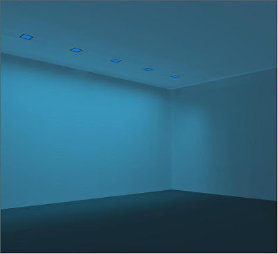
Tuesday, January 11, 2011

DIALux Tutorial 3 RGB Color Changing Scenes


DIALux Tutorial 3 Creating different RGB Color Changing Scenes
This third tutorial explains the following:

1. Creating control group

2. Creating light Scenes

3. Put the right value for the RGB

4. Saving and restoring camera view.

5. changing the light scene in cad

To start this tutorial you have to make an RGBW wall washer line arrangement as explained in the second tutorial where it could be found under the following link


http://ezzatbaroudi.blogspot.com/2011/01/dialux-tutorial2-how-to-make-offset-and.html


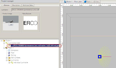
The wall washer for this tutorial is ERCO 37838, but you also can use any other RGB or RGBW (RGB with white light).


After you place ERCO 37838 for one of the wall as explained in tutorial 2, select this arrangement (all the luminaries )in the project manager left side and right click the mouse to open the context menu and then select add to control group then new control group as could be seen form next image


You can change the name of the control group by selecting it in the project manager (left side of the software) and then changing the name form the property window (The Inspector) as shown below.


Select the control group and right click the mouse and select add to light scene then new light scene.


Select the new light scene form the project manager and rename it to red scene form the property window


Then expand the scene list by the clicking on the + sign near the red scene in the project manager

And select wallwasher group inside this list as could be seen form next image


After that put the dimming values shown in the property window zero for all luminous emittance except for the red luminous remittance as could be seen form next image.

The red luminous emittance for this luminaire is the second one, this luminous emittance should remain 100 % the other should be 0%


You can know the color of luminous emittance of an RGB or RGBW luminaire simply by selecting the luminaire second property which shown after you expand the arrangement by clicking on the + sign and selecting the lower row as could be seen in the next image.


Then from the first tab technical data tab you can select the sub-tab luminous emittance form the first to last sub-tab as you can see form next image.


For ERCO 37838 you can read the following information

The first sub tab the color is warm white with 870 and 15 watt

The second sub tab is red with 100 lumen and 3 Watt

The third sub tab is Green with 269 and 5 watt

The fourth sub-tab is Blue with 101 and 5 watt


Also you can open the second tab which is the light colour and see the color of the luminous emittance


Now select the wallwasher control group and add it to a new light Scene and rename the new Scene to Blue Scene


And put the dimming values for all luminous emittance in this scene zero except the blue one as shown below


You can add as many scene as you wish and change the color to the desired color e.g. you can put 5% white, 70% red , 25% green in one scene.

Now let’s try one more new scene for this tutorial.

Add new scene and rename it to cyan and put the following dimming values


Now show the 3D view form the tool bar


And rotate, zoom, move and roam form the tool bar


Until you have a good view of the wall that is being washed by the wall washer like the one below
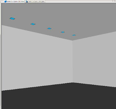


Now save this view so you can see it any time by clicking ctrl key and any number between 1-9, alternately by going to cad menu and then save camera view and then choose save position 1


You can save up to 10 different positions and to restore that position simply press alt key and the number of the poison or form the CAD menu and select the position form redo camera view.


Form the color tab, apply the white color to walls by drag and drop option of the mouse so you can see the reflection of the RGBW colours in a better way.


Now start the calculation


You can change scenes by the tool bar buttons and also you can see the dimming values as you can see in the next image.


Also you can change the scene in the project manager by selecting the required scene and then right click the mouse and select the required scene


Use light scene for CAD as shown in the next image.


Previous DIALux Tutorial

1. DIALux Tutorial 01: Cove light


2. DIALux Tutorial 02: Spacing and offset


Follow me for the latest DIALux Tutorials on my twitter

Saturday, January 8, 2011

Dialux Tutorial_2 How to make an offset and spacing for objects and luminaries

This DIALux Tutorial explains how to


1. Use the help line and help grid
2. Copy along a help line
3. Copy along a line
  1. Insert a photometric file(ies, eulumdat or ULD) to DIALux project
  2. Use the Vertical planar with editing and changing different properties

This tutorial to explain to make an offset and an equal spacing for objects and luminaries inside DIALux by four different methods

I will explain the offset and spacing for wallwashers.

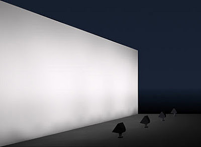
A wallwasher is a luminaire with an asymmetric light distribution placed at an offset from a wall (usually one third of the wall height with a spacing equal to the offset) in the next image you can see a a reseed wallwasher for indoor application.


the first three methods explained in this tutorial for placing the wallwasher are applicable for objects and furniture as well.
Tutorial 02
First make a room with dimension of 5×6 and height of 3 meter and don’t forget to click on OK, otherwise you can’t move to the next step.


You can select any luminaire for this tutorial I have selected an RGBW LED wallwasher form ERCO website the product reference is ERCO 37838
You can put this number 37838 in the search box in ERCO website www.erco.com as shown in the next image
After that you can click on the article appears in the result the red box in the illustration

Then select the Dialux ULD data (i-drop)


Download the file to the desktop

After downloading the file go to the file after you unzipped it and select the file and right click on the mouse to open the context menu and select inset into dialux project as you can see form next illustration.

Now you should be able to see the product in DIALux, in the project manager the luminaire used


Placing the wallwasher for the upper wall in the room.
Method one.
Place a help line form the tool bar

On the upper wall of the room form point one to point 2 as shown in the illustration

While selecting the help line put the offset line Parallels Spaced Apart as 1 meter as shown in the next image

By the way you can create as many offset line as you wish by putting the number in the Number of Parallels in this tutorial keep it one.
If the line goes outside the room you have to put a minus sign before the
number so the direction of the offset will be in the opposite side.
Now you can see an offset line as in the next image

Select a line arrangement form the tool bar

Move the two blue dot of the line arrangement by the mouse to the offset line as you can see form the next image

On the mounting tab (second tab) put 5 in the Quantity and then click on paste button as in the next image


Click on the 3D light distribution display button on the tool bar to ensure that the light is to the wall side as in the next illustration.

If the light distribution on the wrong side then you can select the line and rotate the luminaire form the rotation tab on the project manager.
Method Two
Delete the line arrangement and keep the offset line
Drag a luminaire by the mouse form the luminaire used in the project manager to somewhere in the room

Activate the 3D light distribution display button and select the luminaire and rotate it to the wall side as in the next image

Right click on the luminaire to open the context menu and select the copy along a help line command


Now move the mouse to the offset, When the mouse is above a help line a small hook appears that tells you that this help line can be selected
When the small hook appears click on the help line
After selecting the help line put in distance that appears in the property window in the project manager a value of 1 meter which is the spacing form each luminaire, then click copy button.


Delete the extra luminaire on the side and the one that is placed earlier in the room (as shown in the next illustration in red color) so you can have only 5 wallwasher with an offset form the wall of 1 meter and a spacing of one meter.


Method Three
Delete all the luminaire and the help line as well.
If you see the grid lines then hide it or Deactivate it by clicking on the button show display grid so you can hide the original grid line and you don’t see any grid in the floor plan


Click on the draw help grid form the tool bar as you can see form the next image.


Then click by the mouse on the 3 point shown in the next illustration , make sure it is in the same order, the first point in the right corner

Then the left corner then point 3.


while you are selecting this grid line change the size of it form the window property that appears in the project manager to make the offset 1 meter and the spacing one meter as shown in the next illustration


Drag a luminaire form the luminaire used folder in the project mangare as shown in step one in the next illustration and drop it by the mouse in the point 2 which is in the help grid line and rotate it on the z axis to be in the right direction to the wall.


Select the luminaire and then right click the mouse and select copy along a line as you can see form the next image.


Move the blue dote to the last point as shown in the next illustration and put a value of 4 in the box number of copy in the project manager(the red box in the next image)

Don’t forget to click on the copy button.


Method Four
While the previous methods are applicable for any object and furniture, this method is only for wall washer.
Delete the help grid line and all the Luminaires.
Form the tool bar click on the vertical planner lighting.

Click on the upper wall form the right corner to the left corner as could be seen form the next image.


You can change a lot of properties of this line form the project manager, for example you can change the offset form the distance box in the arrangement tab


You can also change the rotation form the rotation tab


If you want to add more luminaire select the Vertical planar line and then right click the mouse and select edit axes


While you are in the blue line right click again and select add axis


You can add or remove as you want by this way.

Now you have five luminaries


These methods of offset and spacing could be used for indoor or outdoor luminaire or eaven for any object


Previous DIALux Tutorial

1. DIALux Tutorial 01: How to create a cove for indirect lighting.


Follow me for the latest DIALux Tutorials on my twitter